Introduction
A natural tooth is stabilized within the jaw primarily through its root, whereas the crown remains exposed to the oral environment. The interface connecting the tooth to the surrounding gingival tissues is termed biologic width. Inberg and colleagues described biologic width and acknowledged D. Walter Cohen as the originator of the term [1].
The concept is largely derived from the landmark work of Gargiulo, et al. [2] which quantified the dimensions and spatial relationships of the dentogingival junction in humans.
After tooth eruption into the oral cavity, approximately 1.07 mm of connective tissue attachment develops, followed by approximately 0.97 mm of epithelial attachment.
Together with the connective tissue component and the epithelial component, these structures form the gingival sulcus, which measures approximately 0.69 mm (Figures 1a-1c).
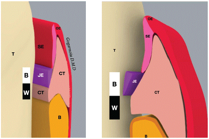
Figure 1a: Illustrates the biologic width complex, showing its overall boundaries and the structural relationships between the epithelial components and the underlying supporting tissues. In particular, connective tissue (CT) is depicted as the predominant supporting structure that underpins epithelial coverage. The diagram highlights the close continuity from the junctional epithelium (JE) and sulcular epithelium (SE) to the oral epithelium (OE), with the tooth and surrounding bone (T, B bone) forming the anatomical basis for the biologic width. Overall, the figure emphasizes that the biologic width occupies 2 mm (BW) and is maintained by the coordinated arrangement of epithelial attachment and connective tissue support. (CT: Connective Tissue; JE: Junctional Epithelium; SE: Sulcular Epithelium; OE: Oral Epithelium; T: Tooth; B Bone: Cortical Bone; BW: Biologic Width 2 mm).
Figure 1b: Illustrates the junctional epithelium (JE) as a circumferential ring of cells surrounding the tooth. In cross-section, the JE has a triangular configuration. At its apex, the epithelium narrows and then extends toward the gingival sulcus, where the base of the JE joins the supporting structures of the sulcus. The base of this triangular JE ends at the level of the sulcus and is composed of approximately 15 cell layers, forming the coronal boundary of the biologic width. The adjacent sulcular epithelium (SE) continues from the JE toward the oral epithelium (OE), with the tooth and surrounding bone (B bone) providing the underlying anatomical frame. (JE: Junctional Epithelium; SE: Sulcular Epithelium; OE: Oral Epithelium; BW: Biologic Width 2 mm).
Although the junctional epithelium (JE) is relatively small in absolute dimension compared with adjacent periodontal tissues, it is regarded as the most dynamic component of the attachment apparatus (Figure 1d).
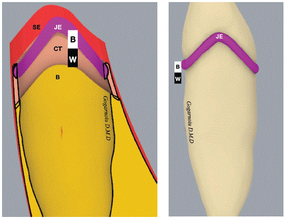
Figure 1c: The biologic width around the tooth is organized according to the enamel junction architectural pathway. From this coronal reference, the organization continues apically and follows the underlying bone architectural pathway. In the healthy state, this alignment corresponds to what is described as a positive architecture.
Figure 1d: Illustrates the junctional epithelium (JE) as the epithelial structure to attach to the tooth. It originates from the reduced enamel epithelium at the completion of amelogenesis during crown formation. During the eruption phase in the oral cavity, the JE remains attached to the tooth at the dental enamel junction (DEJ), closely reflecting its contour.
It dictates where the biologic width it will reestablish under favorable condition away from the source of injury or plaque induce apical migratory response (Figures 1e-1h).
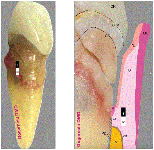
Figure 1e: Microgap created by fracture of the coronal portion of the tooth is associated with a reorganization of the attachment apparatus. This includes changes to the biologic width complex below the fracture line, which reorganizes in a parallel pattern relative to the fracture.
Figure 1f: Close-up of the fracture area, which provides insight into the history of dental treatment. Historically, the biologic width was organized around the CEJ. In the original crown model, the crown preparation followed the CEJ, maintaining a favorable restorative architecture without infringing on this space, as shown in the image.
In contrast, a traumatic event alters the topography of the biologic width, shifting it from a stable crown-and-bridge configuration to a traumatic condition. As a result, the biologic width reorganizes apically toward the fracture line in a pattern that closely parallels the fracture. This is reflected in the change from minimal sulcular epithelium depth in the crown model to pocket epithelium depth in the trauma scenario.
(CEJ: Cemento-Enamel Junction; CR: Crown; CRM: Crown Margin; PDL: Periodontal Ligament; CT: Connective Tissue; OE: Oral Epithelium; PE: Pocket Epithelium; JE: Junctional Epithelium; B Bone: Cortical Bone).
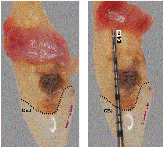
Figure 1g: Post-extraction tooth with evidence of plaque and calculus located below the CEJ. Some pocket epithelium also remains present.
Figure 1h: Evidence of biologic width migration, as a result of the advancement of bacterial plaque and calculus.
The JE provides a protective seal and functions as a selectively permeable barrier between oral environment and underlying tissues. It also supports adhesion to the tooth surface and enables controlled permeability to metabolic products and host defense cells, including polymorphonuclear leukocytes. Apically, the JE comprises a limited number of cell layers, whereas coronally it may extend to approximately 15-30 layers. The JE remains non-keratinized and relatively undifferentiated. The basal layer is mitotically active and forms an interface with the tooth surface and underlying connective tissue, an arrangement described as an “epithelial attachment” by Schroeder and Listgarten [3,4].
Because many periodontal and restorative outcomes depend on preserving the integrity of this interface, an understanding of biologic width is essential for predictable clinical therapy. A key clinical observation is that JE attachment can occur over enamel, cementum, and dentin, whereas bone does not readily accept enamel as a stable substrate.
Analogously, peri-implant tissues also develop a biologically formed and stable configuration that can be considered functionally comparable to natural tooth biologic width [5-7] (Figures 2-4). Early postoperative marginal bone loss of approximately 1.5 mm around dental implants, as reported by Albrektsson, is now commonly attributed to the establishment of peri-implant biologic width [8].
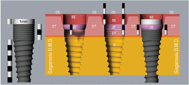
Figure 2: Precise 3D model of a generic implant and the associated biological structures when the biologic width is organized as a supracrestal tissue attachment. The figure labels the key components including the Oral Epithelium (OE), Sulcular Epithelium (SE), Connective Tissue (CT), Junctional Epithelium (JE), and Bone (B).
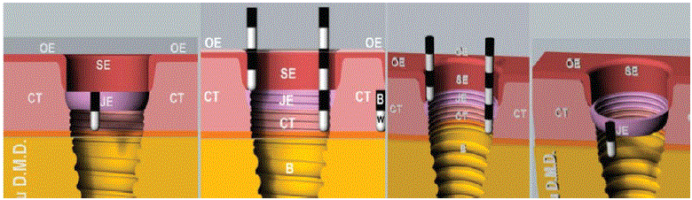
Figure 3: Biologic structures and their spatial relationships to one another, presented without the implant in the field of view. The figure highlights the Oral Epithelium (OE), Sulcular Epithelium (SE), Connective Tissue (CT), and Junctional Epithelium (JE) in Relation to the Bone (B), Demonstrating the Biologic Width (BW) dimension of 2 mm.
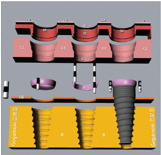
Figure 4: A view of the individual biologic structures associated with the dental implant, presented in an architectural and volumetric expanded representation. The figure highlights the Oral Epithelium (OE), Sulcular Epithelium (SE), Connective Tissue (CT), Junctional Epithelium (JE), and the Bone Components (B Bone and CB Cortical Bone), with the Biologic Width (BW) depicted as 2 mm.
In two-piece implant systems, an anchoring rough-surfaced component is placed in the jaw and subsequently connected to a prosthetic component through an implant–abutment interface (Figure 5a). This interface includes a microgap [9].
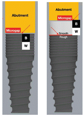
Figure 5a: Location of the microgap at the abutment–implant interface, with the Biologic Width (BW) indicated as 2 mm.
Figure 5b: A microgap can occur alongside a smooth and a rough border within the same implant design, with the Biologic Width (BW) indicated as 2 mm.
In some implant designs, the surface below the interface transitions to include a roughened region, whereas in other designs a smooth portion is present before continuation into a roughened region. At the junction between polished and rough surfaces, a rough-smooth border is formed (Figure 5b).
It is evidence, both the microgap and the rough–smooth border have been shown to influence peri-implant bone remodeling and the spatial establishment of biologic width around two-stage implants. Bone tends to stabilize at the rough-smooth interface rather than on the smooth surface, and then the bone remodels according with the relationship with this interface Consistent findings also indicate that placing either the microgap or the rough-smooth border deeper relative to the bone level is associated with increased bone loss, regardless of implant loading conditions [10,11].
From a clinical perspective, it remains important to clarify which of these two controlling cues initiates remodeling first, namely the microgap or the rough-smooth border, and to determine whether their influences are competing, functionally suppressed, or redundant. These questions can be addressed by varying the distance between the microgap and the rough-smooth border (Figures 6a-6d).
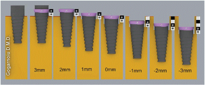
Figure 6a: Illustrates a rough implant surface model, showing a dynamic coronal-to-apical representation of the implant planform at the implantabutment interface from a supracrestal position to a subcrestal position. The figure demonstrates the dynamic accommodation of the biologic width based on the relationship between the implant platform and the bone level, including the Junctional Epithelium (JE) and the Biologic Width (BW) dimension of 2 mm.
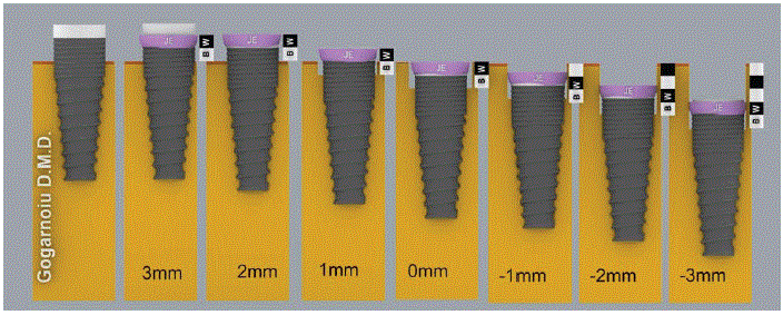
Figure 6b: A rough implant surface model with a 1 mm smooth surface collar. This design behaves similarly to a fully rough implant surface model, following the same remodeling pattern. The microgap remains the leading factor in the remodeling process. The figure also indicates the Biologic Width (BW) as 2 mm and the Junctional Epithelium (JE).
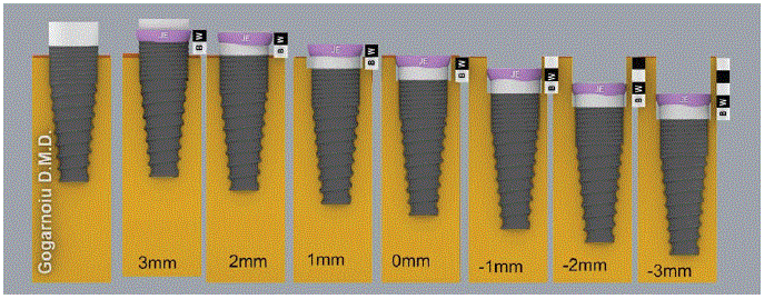
Figure 6c: Illustrates a rough implant surface model with a 2 mm smooth surface collar. In this configuration, the rough–smooth border becomes redundant for bone remodeling at the implant–abutment interface. As a result, this model induces the same pattern of bone remodeling as the fully rough surface model or the 1 mm smooth collar model. (BW: Biologic Width 2 mm; JE: Junctional Epithelium).
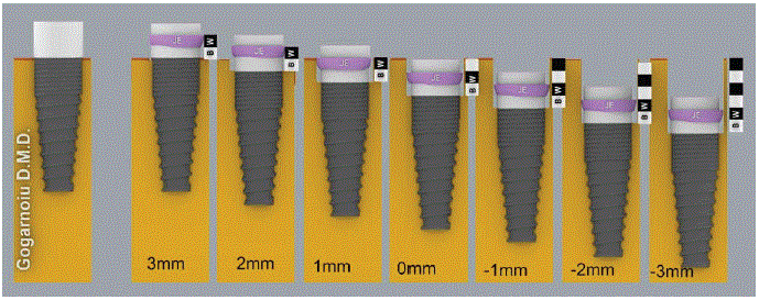
Figure 6d: A rough implant surface model with a 3 mm smooth surface collar. In this configuration, the location of the implant abutment interface relative to the bone level results in the greatest degree of remodeling. This increase is attributed to the larger distance between the smooth-rough border and the implant abutment interface, with the smooth-rough border acting as the primary driver of remodeling. (BW: Biologic Width 2 mm; JE: Junctional Epithelium).
This includes evaluating implants placed perpendicular to the bone level (Figures 7,8) as well as implants placed at an inclination, (Figure 9) across supracrestal to subcrestal positioning in 1-mm increments, with supracrestal and subcrestal positions not exceedingly 3 mm. In addition, remodeling patterns can be evaluated with attention to mesial and distal aspects to determine whether the biologic width formation exhibits region-specific behavior.
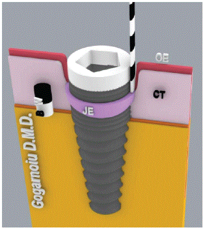
Figure 7: 3D model of the implant and supporting structures (BW Biologic Width 2mm, JE Junctional Epithelium, CT Connective Tissue, OE Oral Epithelium).
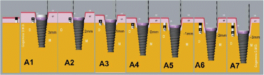
Figure 8: Bone remodeling and an increase in probing depth become significant when the implant is placed 1 mm below the crest of the alveolar bone (Scenario 5) and continue to progress in subsequent scenarios. This process is symmetrical: the Junctional Epithelium (JE) remains parallel to both the bone topography and the implant connection. Subgroups A6 and A7 should be considered high-risk for further biological complications; however, they can still reproduce the aesthetics of the replaced tooth with a favorable emergence angle due to the increased running room.
Materials and Methods
A 3D model of two-stage implant was developed using CAD software. The model includes an anchoring body with a diameter of 4 mm featuring a rough surface and a flat collar exit corresponding to the abutment connection. The coronal portion comprises a 1 mm smooth surface, followed by a 3 mm neck and an 8 mm threaded rough-surfaced body (Figure 2).
The implant is positioned within bone and surrounded by an overlying 2 mm layer representing soft tissue. The underlying bone includes both cortical and cancellous components to reflect periimplant anatomical arrangement.
Multiple dimensions of biologic width (BW) have been reported in the literature, including values that are slightly smaller or larger than 1 mm, for both the junctional epithelium (JE) and the connective tissue (CT).
In this 3D computer model, the BW dimensions were rendered in 1 mm increments to facilitate visualization of BW dynamics. Specifically, a thickness of 1 mm was assigned to each of the connective tissue (CT) and the junctional epithelium (JE). Together, CT and JE form a total BW dimension of 2 mm.
Within this framework, the implant–abutment interface, identified as the microgap, is assumed to have a major influence on bone loss, to create space for BW formation around two-stage implants.
Biologic width and border considerations
The position of the rough-smooth border relative to the bone crest is modeled as a key determinant of the final biologic width location. In accordance with prior findings, bone is expected to stabilize at the rough-smooth border and subsequently remodel according with this landmark position in condition where the border is subcrestally positioned, independently of loading conditions. In designs in which a rough border is present in association with the microgap, or where a smooth collar segment of varying length lies below the microgap, the interaction between competing cues may affect remodeling pathways and consequently influence parameters related to prosthetic development such as emergence angle and the emergence profile.
Perpendicular versus angled implant orientation
An additional aim of this study is to examine how biologic width is re-established when the implant is oriented perpendicular to the bone level compared with an inclined orientation. To assess the combined and potentially competing effects of the microgap and the rough-smooth border, four main scenarios were defined within the model. Each scenario is evaluated using seven subgroups to maintain structured comparison across experimental conditions, with placement depth and border position varied according to the subgroup definitions.
Scenario 1(Figure 6a) evaluates an implant design featuring a rough surface only, such that a smooth surface component is absent. In this scenario, microgap-associated effects on remodeling are assessed across seven subgroups representing supracrestal positions from 3 mm to 1 mm above the bone, at the bone level, and subcrestal positions from 1 mm to 3 mm below the crest.
Scenario 2 (Figure 6b) introduces a 1 mm smooth surface in addition to the rough surface. In this scenario, both the microgap and the rough-smooth border are assessed within the same subgroup framework used in Scenario 1, enabling direct evaluation of how the introduction of a smooth segment modifies remodeling initiation and stabilization.
Scenarios 3 (Figure 6c) and 4 (Figure 6d) increase the smooth surface to 2 mm and 3 mm, respectively, while preserving evaluation within the same seven-subgroup structure. These scenarios are designed to examine remodeling across progressively extended smooth collar lengths under the modeled assumptions of early biologic width formation, without incorporating additional soft tissue complexities beyond those already defined in the overall model configuration.
Orientation sub-studies
To evaluate the effects of implant orientation on biologic width re-establishment, two orientation-focused analyses are included. In the perpendicular orientation analysis, the implant is positioned perpendicular to the bone and evaluated across the same sevensubgroup placement conditions, incorporating both hard and soft tissue parameters. Measurements are obtained in mesial and distal sections to characterize potential regional differences in remodeling behaviour (Figure 7).
In the angled orientation analysis, the implant is placed at an inclination relative to the bone level. Seven subgroups are used to vary angulation-related and depth-related measurements, with assessment performed in both mesial and distal aspects relative to the modeled relationships between the soft and hard tissue boundaries. Throughout both orientation analyses, measurements incorporate the position of the interface width below the microgap, including any contribution from the presence of a smooth surface where applicable, as well as the relative position of the rough-smooth border to the bone crest.
Results
In Scenario 1, the microgap is surrounded by a rough border, and the implant abutment interface is located 3 mm above the bone. Under these conditions, no bone remodeling occurs because the configuration accommodates the 2 mm requirement of biologic width. Similar findings are observed when the interface is positioned 2 mm above the bone.
However, when the implant is placed 1 mm above the bone, bone remodeling occurs to create additional space for the 1 mm connective tissue component. The junctional epithelium is expected to establish in a supracrestal position (1 mm). Consequently, the equicrestal component would require 2 mm of bone remodeling, whereas the subcrestal position (1 mm) would require 3 mm of remodeling. When the interface is placed 3 mm subcrestal, the total extent of remodeling may reach up to 5 mm.
In Scenario 2, adding a 1 mm smooth surface produces a bone remodeling pattern similar to that observed with a rough-surfaced implant alone. This indicates that remodeling is primarily governed by the implant abutment interface. Because this smooth portion contributes only 1 mm, the findings suggest that the microgap associated biologic width requirement of 2 mm plays the leading role in driving remodeling.
In Scenario 3 both have a similar behavior in establishing biologic width considering them redundant.
In Scenario 4, the rough surface demonstrates a dominant effect. When the implant abutment interface is positioned 3 mm below the crest, remodeling increases, reaching approximately 6-7mm. Overall, these results suggest that a smooth surface of about 1 mm (or less) is optimal in implant design, as it helps limit the extent of bone remodeling during subcrestal placement due to the rough-smooth border. Additionally, maintaining the implant abutment interface (microgap) as the primary remodeling driver when biologic width accommodation is insufficient supports this outcome.
As a result, this 1-mm smooth-surface implant design could be used to study the next subject of observation over the next two scenarios. The first scenario (Figure 8) describes mesio distal periimplant tissue changes after implant placement relative to a baseline soft-tissue thickness of 2 mm above the bone crest. Because biologic width (BW) requires 2 mm in total (1 mm junctional epithelium [JE] plus 1 mm connective tissue [CT]), the final tissue dimensions depend on the vertical position of the implant relative to the bone crest. Consequently, the anticipated sulcus depth and the available “running room” for prosthetic emergence vary with placement depth.
In the A1 condition (implant platform 3 mm above the bone), soft-tissue thickness increases to approximately 4 mm, BW occupies 2 mm, and the resulting sulcus depth is 2 mm. This configuration is biologically acceptable; however, establishing an adequate emergence profile prosthetically may be difficult without a connective tissue graft (CT) to provide additional volume and running room.
In A2 (implant 2 mm above the bone), soft-tissue thickness remains approximately 4 mm and BW remains 2 mm, producing a 2-mm sulcus. The JE attachment is positioned higher on the smooth collar.
In A3 (implant 1 mm above the bone), soft-tissue thickness decreases to 3 mm, leaving a biologically acceptable sulcus depth of 2 mm, with the JE/CT re-established near the mid-smooth collar region.
In A4 (equicrestal platform position), soft tissue returns to 2 mm, and bone remodels subcrestally by about 2 mm to re-establish BW (1 mm JE+1 mm CT), producing a 2-mm sulcus. In A5 (1 mm subcrestal), bone remodeling and BW establishment result in greater running room (approximately 3 mm). In A6 (2 mm subcrestal), total remodeling increases to 4 mm and yields a 4-mm sulcus/run-room. In A7 (3 mm subcrestal), total remodeling reaches 5 mm, resulting in a pocket depth of about 5 mm.
For the angled orientation conditions, the second scenario B1-B7; (Figure 9) shows that the model predicts asymmetric bone remodeling when implant angulation is introduced relative to the bone level. Biologic width gradually shifts from a pattern parallel to bone (B1- B2) toward a pattern parallel to the implant abutment interface. This transition results in more remodeling occurring on the mesial side first and the distal side second (B3-B7).
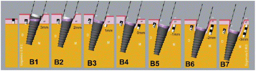
Figure 9: Illustrates interproximal bone remodeling occurring asymmetrically, with greater bone loss on the mesial than on the distal side. Additionally, the Junctional Epithelium (JE) is not parallel to the crestal bone; instead, it aligns with the implant connection. Subgroups B3-B7: Subgroups B6-B7 should be considered high risk for further biological complications, especially on the mesial aspect.
Overall, these results suggest that deeper implant placement increases the required remodeling, which increases sulcus depth and running room. Although this may improve the potential emergence profile, biologically it is not ideal because the inflammatory potential increases due to the more profound asymmetrical remodeling process that occurs when an angle is introduced between the implant insertion direction and the bone-level position.
Looking retrospectively at several clinical cases, the following case confirms the computer model’s central premise: biologic width is the main driver of bone remodeling and plays an integral role in biologically mediated wound healing.
The patient presented with a fracture of the lateral incisor at the gingival margin (Fig.10a). After an atraumatic extraction, the extracted tooth (Figures 10b-10c) showed an almost perfectly circular profile at the fracture level, along with a visible sign of the oblique orientation of the periodontal ligament attachment (Figure 10d).
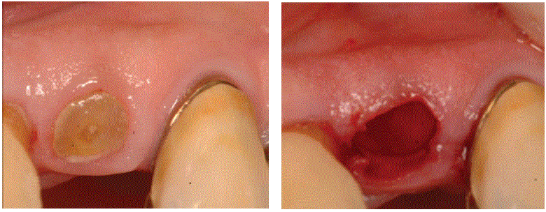
Figure 10a: The tooth fracture at the gingival margin, viewed in cross-section, is almost a perfect circle.
Figure 10b: Tooth extraction with minimal trauma to the surrounding tissues.
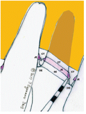
Figure 10c: The artwork facilitates visualization of the soft-tissue attachment after tooth extraction, positioned above the bone in an oblique pattern from mesial to distal. Oral Epithelium (OE), Sulcular Epithelium (SE), Connective Tissue (CT), Junctional Epithelium (JE).
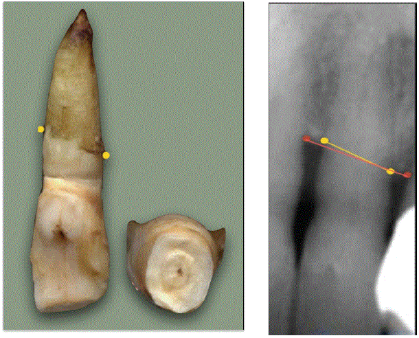
Figure 10d: After extraction, the tooth confirms that the bone and supporting structures are oriented obliquely from mesial to distal, and shows a circular outline of the root at the level of the fracture.
Figure 10e: Radiographically, the bone and supporting structures are oriented obliquely from mesial to distal.
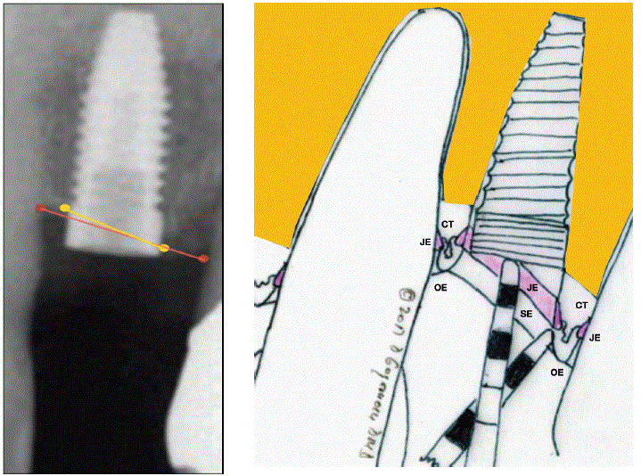
Figure 10f: The X-ray shows the relationship between the implant connection and the crestal bone. Mesially, the connection is positioned supracrestally, whereas distally it is located at the bone level.
Figure 10g: The artwork highlights the significant discrepancy between the flat implant connection and the oblique orientation of the bone and soft-tissue complex (Sulcular Epithelium (SE), Junctional Epithelium (JE), connective tissue (CT), Oral Epithelium (OE)).
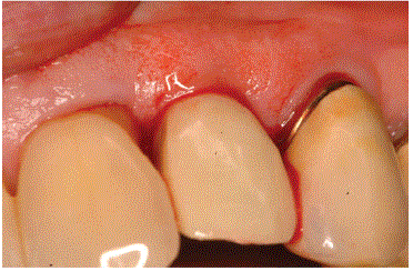
Figure 10h: An immediate provisional crown that preserves the original tooth’s emergence profile.
Radiographs confirmed an oblique orientation of the surrounding bone, consistent with the post extraction tooth evidence of periodontal ligament present on the root in an oblique orientation pattern (Figure 10e).
An implant with a diameter matching the tooth was placed; it was also tapered apically, closely resembling the root shape (Figures 10f-10g).
The implant was immediately provisionalized using a screw-retained provisional restoration (Figure 10h) and, after 3 months, upgraded to a screw-retained implant-supported crown (Figures 11a,11b).
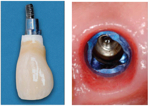
Figure 11a: Final restoration: a screw-retained crown made of porcelain fused to a zirconium substructure.
Figure 11b: Excellent tissue response with a minimal sulcus depth around 360°. The implant size and shape closely matched the extracted tooth, eliminating the need for deep running room to reestablish the original tooth shape.
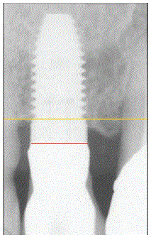
Figure 11c: The X-ray indicates no mesial bone resorption; however, distally, bone remodeling has occurred to accommodate the biologic width. Consequently, the oblique orientation of the bone has changed to a flatter architecture, following the geometry of the implant connection.
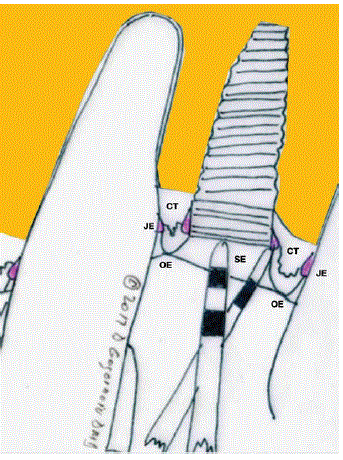
Figure 11d: This change is summarized in this artwork representation (sulcular epithelium (SE), junctional epithelium (JE), connective tissue (CT), oral epithelium (OE).
At the time of implant placement, the implant platform was positioned at bone level on the distal aspect and supracrestal on the mesial aspect. At the delivery of the final crown, bone remodeling was evident distally, whereas the mesial bone level remained unchanged (Figures 11c,11d).
The most plausible explanation is that the mesial microgap was positioned supracrestally, allowing the biologic width to establish supracrestally without requiring additional bone remodeling. In contrast, the distal microgap was located at the equicrestal level, necessitating bone remodeling to accommodate the biologic width (Figures 12a-12c). This clinical pattern is consistent with the B3 scenario, (Figure 13) supporting the correlation between the model predictions and clinical observations.
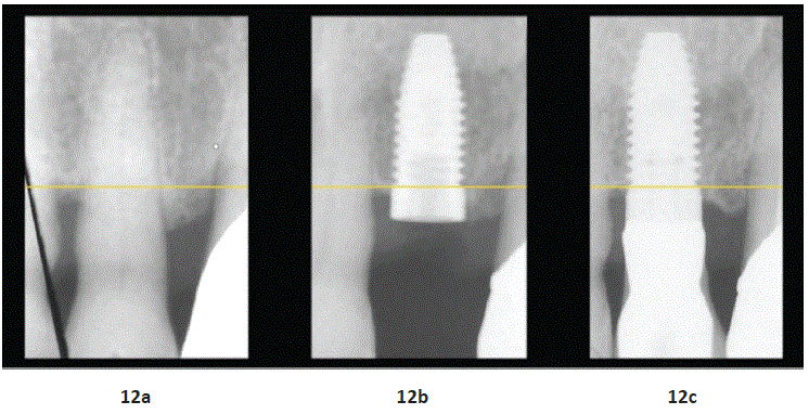
Figure 12: The X-ray illustrates the bone topography associated with the tooth prior to its traumatic fracture (Figure 12a), followed by replacement with an implant (Figure 12b) and a two-year follow-up (Figure 12c). The mesial interproximal bone level remained unchanged in both models. By contrast, the distal bone level remodeled in the implant model to accommodate the biologic width.
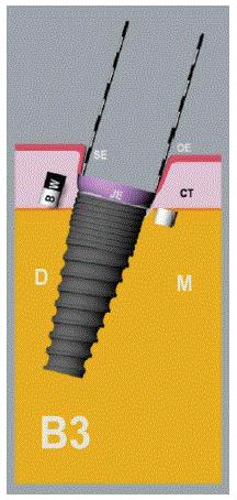
Figure 13: This clinical outcome is similar to computer scenario B3.
A second retrospective clinical case further demonstrates the importance of bone-level orientation in relation to the implant abutment interface.
The patient had an existing fixed dental prosthesis in which teeth 27, 29, and 31 supported retainer crowns, while the missing tooth 30 is replaced by a pontic. Tooth 29 developed recurrent caries (Figure 14). The prosthesis could be safely removed to provide direct access to the tooth. The affected tooth was extracted, and an implant was immediately placed (Figure 15).
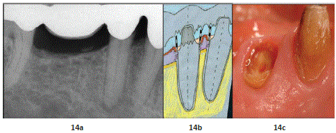
Figure 14: X-ray of a tooth-supported bridge shows periapical radiolucency at the second premolar (a). It provides baseline information: the retainer crown outlines the level and shape of the supracrestal soft-tissue attachment, which can be suggested but not visualized (b). Visualization of the supracrestal soft-tissue attachment including the emergence profile and sulcus depth is shown after bridge retrieval, along with recurrent decay that consumed most of the abutment tooth up to the gingival margin (c).
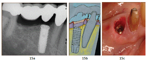
Figure 15: The X-ray shows implant placement following the previous tooth position, with the implant platform positioned equicrestal on the distal aspect and subcrestally on the mesial aspect. The bridge also highlights the differences between the current implant shape and position and those of the former tooth (a). The artwork allows visualization of the previous.
A provisional custom abutment was fabricated and immediately loaded into the existing prosthesis (Figure 16). At 3 months, a scan replica was taken (Figure 17).
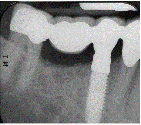
Figure 16: Radiographic view of an immediate provisional abutment retrofitted into the existing bridge.
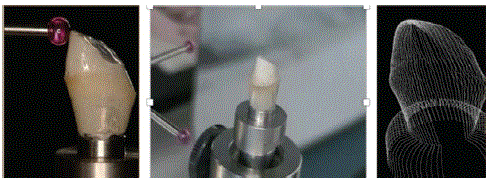
Figure 17: The abutment was scanned using a touch scanner after 3 months in function. The touch scanner provides high accuracy in reproducing the prototype of the custom abutment that will be retrofitted into the existing bridge.
The abutment was fabricated in zirconium and retrofitted into the existing bridge (Figures 18,19). This approach permitted evaluation of bone remodeling as the attachment relationship shifted from a toothoriented attachment level to an osseointegrated implant-supported level.
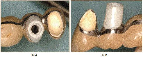
Figure 18: A perfect fit and a highly revealing result for analyzing the transition from the bridge reflecting the original organic tooth shape to the geometrically simple implant abutment, which is round and flat and positioned at a much deeper apico-coronal level.
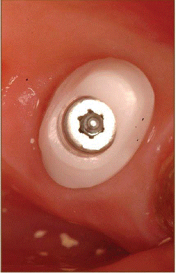
Figure 19: The zirconia abutment in place prior to the radiographic evaluation of abutment fit to the implant and bridge.
Radiographically, the implant was positioned equicrestal on the distal aspect and subcrestally on the mesial aspect. Asymmetry in remodeling was observed: distal and mesial bone changes were not equivalent, with greater remodeling occurring mesially than distally (Figures 20,21).
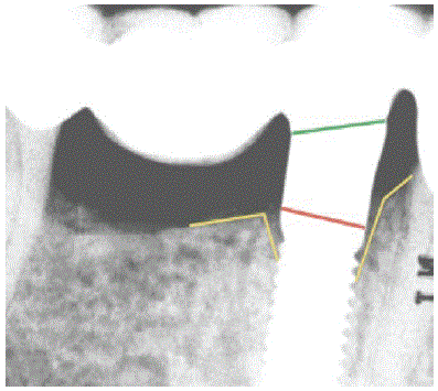
Figure 20: Radiographically, the abutment fits both the implant and the bridge and allows evaluation of the transition from an obliquely oriented attachment around the tooth to a flatter.
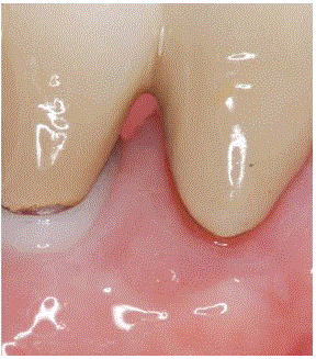
Figure 21a: Evidence of soft-tissue loss compared with the previous tissue around the tooth, as reflected by the bridge (the past condition). Not only was the papilla lost, but the tissue around the tooth was also slightly reduced compared with the tissue around the zirconia implant abutment.
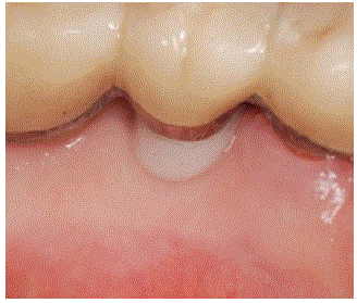
Figure 21b: Lingual view of the tissue level around the abutment, showing how the tissue level in the past (when the tooth was present) compares with the tissue level now, following replacement with a dental implant.
The existing bridge also highlighted the extent of soft-tissue remodeling associated with subcrestal placement. Specifically, subcrestal positioning on the mesial aspect of the implant affected the attachment level of the neighboring tooth, resulting in papilla loss between the implant and the adjacent tooth [12] (Figures 22a,22b).
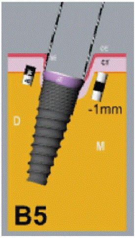
Figure 22: This clinical outcome is similar to the computer simulation in the B5 scenario.
Overall, the biologic width configuration changed from an oblique orientation associated with the natural tooth and its bone level to a flatter orientation reflecting the implant abutment interface (Figure 20). This dynamic is well represented by the computer model. This pattern aligns with Scenario B5 (Figure 22).
Discussion
Although biologic width was originally described in relation to the tooth and its peri-prosthetic/periodontal environment [13-15] it later gained significant relevance in dental implantology. Dental implants have been used for decades to replace missing natural dentition and to serve as anchors for prosthetic restorations. While ongoing debate remains regarding similarities and differences between the biologic width in tooth versus dental implant models, this article highlights their shared function as a protective barrier between the oral environment and the underlying attachment apparatus.
One of the most important determinants of long-term implant success is peri-implant bone loss. This process may result from multiple etiologic factors described in the literature [16-19].
As a consequence, identifying the underlying cause(s) and translating them into an appropriate treatment plan can be challenging.
The focus in this article is on the biologic width formation rather than strictly equating biologic width formation with physiologic bone remodeling or with the development of the supracrestal tissue attachment (SCTA).
These latter equivalences do not adequately convey how biologic width is structured and how it forms. As shown in the computer model, supracrestal tissue attachment occurs only when the implant is positioned sufficiently supracrestally to accommodate the dimensions of biologic width. When the implant is placed subcrestally, the tissue attachment should therefore be termed subcrestal tissue attachment, because the biologic width it establishes subcrestally. Accordingly, what is often termed “physiologic bone remodeling” can be understood as the process that enables biologic width to establish at a position determined by the implant abutment interface or by the rough-smooth border when the implant is placed equicrestal or subcrestally.
Accordingly, biologic width formation should be considered a key step in osseointegration, because it can substantially influence the long-term success or failure of dental implants.
The tooth is architecturally complex, whereas the implant is geometrically simpler; however, it remains highly challenging for peri-implant tissues to achieve functional and esthetic integration comparable to natural dentition.
Because the dental implant must ultimately connect to a prosthetic crown once it has been successfully osseointegrated, the functional and esthetic outcomes of therapy are determined by this connection.
This connection may represent a clinical liability, particularly in relation to its ability to transition successfully to the oral environment.
At the microstructural level, the microgap and the surface topography including the smooth-rough border have been proposed as influential determinants of bone remodeling.
As the computer model shows increasing, the dimension of the smooth surface beyond 2 mm reduces the influence of the microgap as a leading factor in remodeling.
This finding supports the idea that the soft-tissue level with a smooth collar beyond 2mm in esthetic-zone protocols may induce more remodeling compared with implants lacking a smooth collar (so-called bone-level dental implants).
We also consider soft-tissue behavior in relation to the vertical position of the implant–abutment interface, or implant platform.
In computer models, supracrestal platform placement increase softtissue thickness (approximately an additional 2 mm) maintaining the bone level as it is.
In contrast, bone-level or subcrestal platform placement tends to preserve the baseline soft-tissue thickness while allowing bone remodeling to occur according to the depth of implant placement.
It is suggested that the presence of increased soft-tissue thickness before surgical implant placement may stop bone remodeling underneath implants that are subcrestally placed [20,21]. This phenomenon is clearly not possible in these computer model scenarios. It could be said that improving the phenotype helps with the development of a tissue volume that supports an emergence profile compatible with the tooth that was replaced by the dental implant, especially in the posterior area of the dentition.
It can be said that from a biological point of view supracrestal placement is most favorable because no bone remodeling occurs, although it can make it difficult to reproduce the form of the original tooth that needed to be replaced.
Conversely, subcrestal placement may lead to increased inflammatory infiltrate [22] while simultaneously enabling a closer approximation of the prior tooth form. Many articles had explored this topic, including debate over emergence profile, available space (“running room”), and emergence angle [23-27].
These factors are often discussed as contributing etiologies for bone loss; however, they may be considered inconveniences to biologic width stability or formation, requiring the complex to migrate or establish toward a biologically compatible position that accommodates both hard and soft tissues.
Today, clinical strategies increasingly aim to create a soft-tissue environment that improves resistance to displacement (KT keratinize tissue) [28,29] and supports tissue volume formation (CTG connective tissue graft) to enhance esthetic outcomes [30-32]. However, such approaches may remain biologically compromised when excessive pocket depth or tunneling occurs [33].
Under appropriate conditions, an anaerobic environment associated with these conditions and occlusal trauma may threaten peri-implant tissue health and, ultimately, implant survival.
Platform-switching implants [34] are widely promoted in the literature as preserving or limiting peri-implant bone loss. However, the author considers that creating and analyzing a 3D computer model version of this implant design would likely produce a similar overall outcome regarding both the microgap and the smooth-rough border. From a biologic width formation perspective, the implant abutment interface must be precisely aligned with the bone level to allow a horizontal establishment of the biologic width with no bone remodeling. When the implant platform is positioned at an angle relative to the bone level, bone remodeling will become asymmetrical, which differ from the expected behavior in a well-aligned platform bone relationship (Figure 23).
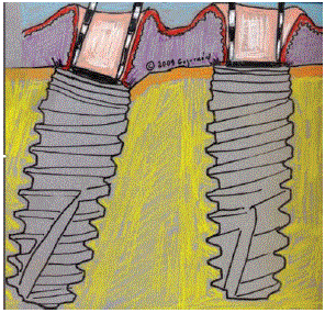
Figure 23: Asymmetrical remodeling in a platform-switch implant when the implant is positioned at an angle relative to the bone level (visual comparison).
In addition, platform switching reduces the platform size, thereby shifting the starting point of the prosthetic emergence profile for the restored tooth. In most cases, this design feature requires a more apical positioning of the implant platform to adequately reproduce the tooth form.
Although the implant is designed to be perfectly perpendicular to the bone level, variations in subcrestal placement associated with a flat implant connection design can promote bone remodeling. This remodeling may lead to differences in sulcus depth and bone-level configurations as the peri-implant tissues adapt to the biologic width formation process (Figure 24).
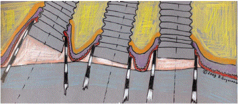
Figure 24: Variations in sulcular depth as a reflection of the position of the implant-abutment interface in relation to the bone level.
Conclusion
This 3D computer-assisted model study is expected to clarify the relative contribution of microgap-related and rough-smooth border-related cues to peri-implant bone remodeling and biologic width formation. By systematically varying the spatial relationship between these two features and evaluating both perpendicular and angled implant orientations, the model provides a framework for understanding how remodeling initiates and how final tissue adaptation may stabilize at specific levels. In addition, the mesio– distal analysis highlights that biologic width formation may not occur symmetrically under all conditions. Overall, the findings underscore the need to consider both implant–abutment interface positioning and transmucosal roughness transitions when planning implant position to support biologically compatible and prosthetically achievable outcomes.
Acknowledgment
The author declares that there is no conflict of interest. This study was conducted in his private office and was supported by the author.