
Figure 1: Means ± SD of the alteration of vertical implant bone level (IBL).

Hadi Gholami1* Regina Mericske-Stern2 Peter Jöhren3 Norbert Enkling4,5
1Assistant Professor, Department of Prosthodontics, Tufts University, School of Dental Medicine, Boston-MA, USA*Corresponding author: Hadi Gholami, Assistant Professor, Department of Prosthodontics, Tufts University, School of Dental Medicine, Boston-MA, USA, Tel: +1 (617)636-6930; E-mail: hadi.gholami@tufts.edu
Objectives: Placing self-tapping implants in High-density Bone (HDB) could increase the cortical stress during implant insertion enhancing periimplant bone resorption. There is a general consensus to avoid self-tapping implants use in HDB. This study assesses the success rate and clinical outcome of self-tapping implants in dense bone.
Materials and Methods: This prospective single-blind controlled clinical trial was conducted on 26 patients who received 2-5 implants in the posterior mandible. Drilling protocol was adapted with the quality of existing bone. Patients were examined at the time of surgery (T1), 3 months post-operation (T2), 4 months post-surgery (T3), 12 months post-surgery (T4), 25 months post-surgery (T5) and 38 months post-operation (T6). Standardized radiographs were obtained at all time points. Three observers measured the crestal bone level changes. Data was analyzed using nonparametric statistics.
Results: The success rate was 100% 3 years after placing self-tapping implants in HDB. Mean bone loss of -0.56 mm (CI 95% -0.69; -0.42) was observed from the time of surgery to the delivery of the crown. After the healing period during functional loading (at 4 to 38 months) there was only a mean bone level alteration of less than -0.04 mm per year.
Conclusion: In this clinical study, all 90 self-tapping implants that have been placed in type I and type II bone were successful 3 years after placement, with minimal crestal bone level changes.
Clinical relevance: Self-tapping implants can be successfully placed in HDB. However, clinicians must be aware of using a bone quality adapted drilling protocol.
Bone level; Bone loss; Dental implants; Implant design; Implant success; High-density bone
Osseointegrated implants are now successfully used to restore function in fully or partially edentulous patients. Use of endosseous dental implants for the replacement of missing teeth has become increasingly popular during the past 30 years. Implants placed in bone of optimal quality and quantities have led to excellent results with successful clinical outcomes [1]. However, the long-term success is less predictable in cases where the implant is placed in bone of poor quality (i.e. soft bone) [1] or quantity (i.e. limited bone volume) [2]. Bone mineral density can greatly affect screw performance [3] and plays an important role in subsequent success or failure of implant treatment. Density (quality) of bone structure in the implant placement area varies from site to site and person to person.
Dental implants placed in the mandible have been shown to have a higher survival rate compared to maxillary implants. The anterior region of the mandible carries the greatest survival rate of implants due to having the densest bone. Posterior region of the maxilla has the highest rate of implant failure attributed to the insufficient bone volume and/or density [4]. Therefore, evaluation of bone structure prior to implant placement is critical to its survival.
Several methods have been proposed for clinical evaluation of bone quality either prior to or during endosseous implant placement by tactile perception of site-preparation [5]. For classification of quantity and quality of alveolar bone, Lekholm U and Zarb GA [6] radiographically categorized bone density into 4 groups based on the volume of cortical bone compared to trabecular bone. The authors classified type 1 bone when “the entire jaw is comprised of homogenous compact bone;” type 2 bone when “a thick layer of compact bone is present surrounding a core of dense trabecular bone;” type 3 bone when “a thin layer of cortical bone surrounds a core of dense trabecular bone;” and type 4 when “a thin layer of cortical bone surrounds a core of low density trabecular bone” [7].
Another classification was offered by Misch CE [8] who correlated the bone density to the bone clinical hardness as subjectively perceived during the drilling procedure prior to implant insertion. D1 bone is “oak or maple-like”, and D2 is “similar to spruce or white pine wood”. According to Misch’s classification, D1 and D2 bones are usually found in the mandible and the anterior maxilla. Truhlar RS, et al. [9] modified the classification of Leckholm U and Zarb GA [6] in their study by adding the tactile sensation during drilling. They also found the densest bone in the anterior region of mandible followed by the posterior mandible, anterior maxilla, and posterior maxilla [9].
The configuration and design of implant body (both macro-design and micro-design) is another parameter that can affect implant success or failure [10]. Self-tapping implants were first introduced to the market in 1983. This modification of implant design has eliminated the need for tapping during implant insertion. It has been demonstrated by Olsson M, et al. [11] and Ivanoff CJ, et al. [12] that the primary stability of implants has improved with self-tapping implants especially in highly cancellous low density bone since the implant compresses the surrounding spongy bone and increases the density of peri-implant bone. However, over compression of the bone structure adjacent to the implant insertion site can have a negative effect leading to implant failure, though more clinical data and studies are needed on this subject matter. Some studies have shown that implant loosening can be caused by formation of collagen-rich connective tissue capsule around the implant due to higher pressure while drilling [13]. The same may occur when self-tapping implants are placed in high density bone that is mainly comprised of cortical bone as this type of bone is more resistant to deformation due to having higher modulus of elasticity and low blood supply [14]. These characteristics decrease the ability of load distribution and increase the susceptibility to bone necrosis of the dense cortical bone compared to trabecular bone as the result of application of excessive torque at the time of implant placement [15]. Unintentionally high or excessive torque applied when inserting the implant can result in excessive compression of the cortical bone causing microdamage, which is a permanent deformation of the microstructure of loaded cortical bone in the form of fatigue and creep. These microdamages can manifest histologically as microcracks, which are discontinuities of the calciumrich bone matrix surrounding implants [15]. According to some orthopedic studies, microcracks are irreversible and can subsequently result in loosening or failure of implants [16].
Placement of self-tapping implants in compact bone also has a risk of bone necrosis due to excess heat generation [17]. Necrosis of the bone contributes to osteolysis around the implant resulting in loss of stability. It has been reported that impaired bone generation occurs when the healing process is compromised as the bone is exposed to 47°C heat for 5 minutes or 50°C heat for 1 minute [18]. This unwanted temperature rise during implantation is greater in compact bones [19].
Efficacy of self-tapping implants in soft bone quality has been very ellw documented while limited evidence is available on the efficacy of self-tapping implants in hard bone quality [10]. The present study sought to assess the success rate and clinical outcome of self-tapping implants in dense bone.
This prospective single blind controlled clinical trial was conducted on 26 subjects according to sample size calculations. A total of 2-5 implants were inserted for each patient in the posterior mandible. Patients were evaluated and examined at the time of surgery (T1 or baseline), at second-stage surgery which was 3 months post-operation (T2), at the time of suprastructure placement which was 4 months post-surgery (T3), at first recall which was 12 months post-surgery (T4), at second recall (T5) which was 25 months post-surgery and at third recall (T6) which was 38 months post-operation. Standardized radiographs were obtained at all time-points.
Twenty-six patients (13 females, 13 males with a mean age of 50.7 ± 10.5 years) presenting to the Dental Clinic Bochum/University of Witten/Herdecke, Germany were enrolled in this study. Patients with good general health and no systemic disease, no drug intake, no pregnancy or nursing, adequate bone quantity to accommodate 9.5 mm length and 4 mm diameter implants, 4 mm of keratinized mucosa in the buccolingual aspects of the implant site and medium or thick soft tissue biotype (i.e. crestal mucosa thickness ≥ 2 mm according to Fu JH, et al. [20]) were included. To assess the adequacy of bone quantity for implant placement, two observers separately assessed bone dimensions and expressed their opinion regarding the adequacy or inadequacy of the residual bone for implant placement. The two observers agreed on this topic in all cases and the Kappa coefficient was calculated to be 1. The width of alveolar process was measured with the bone mapping technique; a process that confirms adequate dimension of bone exists prior to implant placement. Bone mapping quantifies the thickness of the ridge (mm scale) throughout the implant site by taking several measurements of the ridge crest and 7 mm vertically to that point [21]. The teeth had to be extracted at least 6 months earlier and implant site had to be free from infection and extraction residue.
Patients with compromised medical health or those with poor compliance to treatment, previous tumors, chronic bone disease or undergoing irradiation of the planned treatment site were excluded from this study. Those undergoing augmentation procedures such as bone grafting or guided bone regeneration were also excluded.
SICace implant system (SIC-Invent, Basel, Switzerland) was used in this study. This implant system has an internal hex connection with an interlocking clearance fit [22] and a medium-rough sand-blasted, acid-etched surface including the implant collar. The implants used had a 9.5 mm height and a 4 mm diameter. The abutment platform was shifted from 4-3.3 mm diameter providing a 0.35 mm circular step (Figure 1). The circular step surface was machined. The diameter of the cover screws was 3.3 mm. Thus, the cover screw had a platformswitched outline.
Figure 1: Means ± SD of the alteration of vertical implant bone level (IBL).
Radiographic follow-up of patients was carried out at all timepoints by taking 6 standardized digital panoramic images (OPGs) using Promax PRX232574 (Planmeca, Helsinki, Finland). For the purpose of standardization, the mandible of patients was fixed with a custom-made bite splint and the unit was individually adjusted based on each patient’s position. DIMAXIS software 4.3.1 (Planmeca) with a measuring precision of 0.01 mm was used for radiographic measurement and analyses. The areas of interest on the radiographs were magnified with 20 × magnification using the software tools and bone height measurements were calibrated at 9.5 mm implant length. Crestal bone level was measured at mesial and distal surfaces of implants. Implant shoulder was considered as the Reference Point (RP) for these measurements. The other units measured were as follows: IBL (vertical implant bone level with the micro-gap as the RP), which is defined as the vertical distance between the micro-gap and the most coronal bone to implant contact and GBL as the general horizontal bone level (Figures 2 and Figure 3). Changes of the crestal bone level over time are expressed as differences of the measured values: ΔIBL and ΔGBL. For statistical analyses, the mean values of mesial and distal measurements were used. Three calibrated dentists experienced in oral radiology independently performed the radiographic assessment. If the differences in the measurements by the three examiners were 0.1 mm or less, the mean of the three measurements was used. If the differences were more than 0.1 mm, the three examiners were asked to re-analyze the specific implant together to reach a consensus.
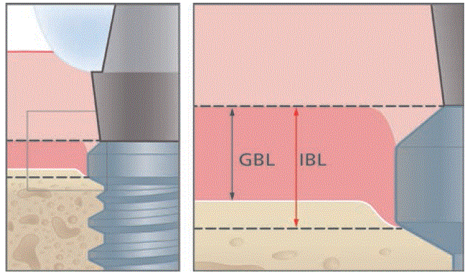
Figure 2: The measured distances at the radiographs: The red area demonstrates the bone-level alteration since baseline (implant insertion operation). IBL, vertical bone level at the implant (reference point: implant platform); GBL, general horizontal bone level (reference point: implant platform).
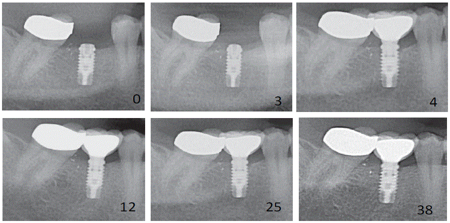
Figure 3: Examples of radiographs taken from standardized panoramic images indicating implant placement (baseline) and 3,4,12,25, and 38 months postoperatively.
Bone shape and density were determined based on preoperative radiographs. Bone density was classified using the Lekholm U and Zarb GA classification system described in 1985 [6].
Local anesthesia was induced by injection of the anesthetic agent (Ultracain UDS forte, Epinephrine 1:100,000, Sanofi-Aventis, Paris, France). A crestal incision was made, followed by the elevation of a full-thickness flap exposing the surgical site. According to the manufacturer’s instructions and presurgical assessment, and on perception of bone density, the drilling protocol was modulated to obtain the so-called adapted drilling. The tapping drill was used for placement of implants in bone with type 1 density (approximately 40%). The tapping drill was not used for type 2 bones. Implants were aligned at bone level with a minimum distance of 3 mm from one another. Surgical re-contouring of the alveolar bone was not carried out and Implant insertion torque did not exceed 50 Ncm. The implants were left submerged for a 3 month healing period. After the placement of implants and the second-stage surgery the patients were asked to rinse their mouths with 0.2% chlorhexidinegluconate mouthwash (Meridolperio, GABA, Therwil, CH) for 1 minute twice a day for 1 week until the sutures were removed. Mechanical cleaning at the implant sites was not allowed for patients 6 weeks after implant placement and 2 weeks after the second stage surgery. Appointments were scheduled at 1 and 2 months after surgery in order to control wound healing, gingival health (full-mouth Sulcular Bleeding Index (SBI) [23]) and oral hygiene (full-mouth Plaque Index (PI) [24]). Submerged implant was re-entered by raising a small full-thickness flap 3 months after the implant placement. Impressions were taken 2 weeks later followed by the try-in of the casted crown frameworks after 1 week. Seven days later (4 months after implant surgery), full ceramic-veneered, casted single crowns were fabricated, SICace standard titanium abutments (SIC No. 936163) were tightened on the implants using 20 Ncm force. Crowns were mounted on the abutments with temporary cement. Oral hygiene of patients was closely monitored at all time-points as well as oral health and implant status. Oral hygiene of patients was also reinforced by hygiene re-instruction, or professional plaque control if necessary every 6 months.
The criteria for implant success used in this study were those described by Albrektsson T, et al. [25]. According to them, a successful implant is characterized by:
The primary outcome variable was changed IBL between BL and 3 years after surgery. The primary hypothesis of this study was that IBL changes were less than 1.1 mm, i.e. significantly less (0.4 mm) [26] than success criterion (1.5 mm) [27] when using self-tapping implants in both bone type I and II. The secondary hypothesis was that bone loss is not significantly different in type I bone compared to type II and is time-dependent. A global test of the dependence of the IBL value on time and bone hardness using the non-parametric model of Brunner E, et al. [28] was performed in a descriptive manner. Sample-size was calculated as 24 patients using G*POWER 3 [29] for achieving a power of 80%. Considering the possible dropouts, 26 subjects were included in the study. This estimate was based on a two-tailed test of matched pairs conducted at the 5% level of significance.
Based on the available literature [30], a bone loss of 0.7 mm with a standard deviation of 0.75 is usually expected after 3 years of having implants in function. The SAS 9.2 software (SAS Institute, Heidelberg, Germany) was used. Graphs were prepared with the PRISM 4 software (GraphPad Software Firma, La Jolla,CA, USA).
After the healing period, all inserted implants were clinically stable and no implant failure or patient drop out were recorded during the follow-up period; thus, the survival rate was 100%. The peri-implant condition was healthy in all subjects. There was no bleeding on probing around the implants and patients had favourable oral hygiene. After delivery of the crowns, good oral hygiene was observed with a plaque index of 0.52 (CI 95% 0.46; 0.58) and bleeding index of 0.37 (CI 95% 0.32; 0.42) (Table 1). No significant changes in probing depth measurements around the implants were observed. The mean probing depth was 2.39 (CI 95% 2.34; 2.44) (Table 2). Minimal bone loss of -0.56 mm (CI 95% -0.69; -0.42) was observed from the time of surgery to the delivery of the crown. During the 34 months after loading, the additional bone loss was averagely -0.08 mm (CI 95% -0.20; 0.04) (Figure 2). Table 3 shows bone level changes (mm) at all time-points. A negative value at the Y-axis indicates that the most coronal bone to implant contact was more apical than the implant shoulder and vice versa.
| Index: Months Postoperatively |
Mean | SD | Minimum | Maximum |
| Plaque Index | ||||
| 0 | 0.55 | 0.32 | 0.18 | 1.38 |
| 3 | 0.52 | 0.33 | 0.14 | 1.38 |
| 4 | 0.45 | 0.29 | 0.07 | 0.97 |
| 8 | 0.28 | 0.21 | 0 | 0.73 |
| 12 | 0.36 | 0.23 | 0 | 0.86 |
| 25 | 0.39 | 0.18 | 0.02 | 0.72 |
| 38 | 0.35 | 0.20 | 0.04 | 0.69 |
| 0 | 0.55 | 0.32 | 0.18 | 1.38 |
| Bleeding Index | ||||
| 0 | 0.34 | 0.27 | 0 | 0.90 |
| 3 | 0.52 | 0.40 | 0 | 1.00 |
| 4 | 0.32 | 0.24 | 0 | 0.90 |
| 8 | 0.21 | 0.19 | 0 | 0.80 |
| 12 | 0.25 | 0.24 | 0 | 0.83 |
| 25 | 0.31 | 0.25 | 0 | 0.90 |
| 38 | 0.29 | 0.30 | 0 | 0.88 |
Table 1: Full-Mouth Plaque Index (Silness J and Loe H [24]) and Sulcular
Bleeding Index (Muhlemann HR and Son S [23]).
SD: Standard Deviation
| Time (months post OP) | Mean | SD | Minimum | Maximum |
| 8 | 2.35 | 0.42 | 1.50 | 3.00 |
| 12 | 2.39 | 0.50 | 1.25 | 3.00 |
| 25 | 2.82 | 0.52 | 1.75 | 3.50 |
| 38 | 2.74 | 0.53 | 1.75 | 3.50 |
Table 2: Mean probing depth (PD) at studied implants.
SD: Standard Deviation
| All Implants (N=96) | Bone Type I (N=45) | Bone Type II (N=51) | |||||||||||
| Time | Measured Distance | Mean | SD | Median | 95% CI for the median | Mean | SD | Median | 95% CI for the median | Mean | SD | Median | 95% CI for the median |
| 3 Months T1 | ∆IBL | -0.39 | 0.41 | -0.37 | -0.55; -0.10 | -0.45 | 0.52 | -0.45 | -0.61; 0.00 | -0.32 | 0.43 | -0.30 | -0.45; -0.10 |
| ∆GBL | -0.26 | 0.38 | -0.27 | -0.38; 0.00 | -0.3 | 0.21 | 0.20 | -0.05; 0.00 | -0.16 | 0.33 | -0.17 | -0.38; 0.00 | |
| 4 Months T2 | ∆IBL | -0.56 | 0.50 | -0.57 | -0.70; -0.20 | -0.61 | 0.42 | -0.59 | -0.69; -0.21 | -0.42 | 0.55 | -0.39 | -0.80; -0.20 |
| ∆GBL | -0.24 | 0.46 | -0.11 | -0.27; 0.00 | -0.27 | 0.25 | -0.21 | -0.29; 0.00 | -0.20 | 0.46 | -0.10 | -0.27; -0.05 | |
| 12 Months T4 | ∆IBL | -0.61 | 0.55 | -0.63 | -0.92; -0.43 | -0.68 | 0.35 | -0.61 | -0.90; -0.28 | -0.57 | 0.55 | -0.48 | -0.82; -0.23 |
| ∆GBL | -0.28 | 0.47 | -0.18 | -0.37; 0.00 | -0.34 | 0.35 | -0.30 | -0.50; 0.00 | -0.19 | 0.47 | -0.18 | -0.37; 0.00 | |
| 25 Months T5 | ∆IBL | -0.64 | 0.65 | -0.64 | -0.77;-0.51 | -0.72 | 0.35 | -0.73 | -0.82;-0.45 | -0.57 | 0.80 | -0.60 | -0.69; -0.40 |
| ∆GBL | -0.26 | 0.63 | -0.28 | -0.41; -0.10 | -0.33 | 0.45 | -0.35 | -0.50; 0.00 | -0.21 | 0.72 | -0.19 | -0.42; -0.10 | |
| 38 Months T6 | ∆IBL | -0.74 | 0.60 | -0.70 | -1.02;-0.50 | -0.81 | 0.43 | -0.78 | -0.87;-0.40 | -0.66 | 0.58 | -0.63 | -0.19;-0.29 |
| ∆GBL | -0.36 | 0.56 | -0.32 | -0.61;-0.15 | -0.36 | 0.45 | -0.35 | -0.65; -0.15 | -0.32 | 0.50 | -0.32 | -0.45;-0.20 | |
Table 3: Mean bone level changes (mm) at all time points after surgery.
After the healing period during functional loading (at 4 to 38 months) there was a minimal mean bone level alteration of -0.04 mm per year.
Technical complications did not occur, but 2 crowns exhibited minimal chipping of the ceramic veneering.
The primary hypothesis was accepted (P<0.001) (post-hoc power: 99.4%): On average, the STI in HDB showed a peri-implant crestal bone loss that was statistically and clinically reduced compared with the accepted implant-success-criteria.
The secondary hypothesis was also accepted, as bone level alteration depended on time (P<0.001) but not on bone-type (P=0.348) and not on the interaction of time and bone-type (P=0.945).
In literature, early implant success is defined as successful outcome of implants for 1 to 3 years. Based on this statement, we may state that our understudy implants fell into the category of early implant success [31].
Dental implants generally have a high survival rate: on average, only 2.5% of all implants placed are lost before loading. After loading, the failure rate is 0.5-1.3% per year [32]. Albrektsson T, et al. [25] proposed a widely used criterion for evaluation of the success of dental implants. One criterion states that the in the first year of service, crestal bone resorption should be less than 1.5 mm and the bone loss should not exceed 0.2 mm annually thereafter. Astrand P, et al. [26] considered a true difference of 0.4 mm to be of clinical importance. In our study, we added this measure together to that of Albrektss on success criterion to determine whether the successful outcome of self-taping implants in high-mass bone is clinically substantial. Radiographic crestal bone loss less than 2.0 mm in comparison with the implant insertion surgery is another criterion suggested by Misch CE, et al. [31]. However, due to the advancements in implantology during the recent years, this rate has further decreased for different implant systems. A metaanalysis [33] reported marginal bone loss of 0.24 for Astra Tech, 0.75 for Branemark and 0.48 for Straumann implant systems at 5 years of loading. These changes between implant systems may be attributed to different thread design.
On the other hand, bone loss following implant insertion is associated with several factors such as ΔGBL; which was 0.26 in this study; 50% vertical bone loss value was attributed to GBL because flap elevation for implant placement or at the second stage surgery can lead to bone resorption [34].
Friberg B, et al. [33] reported a 100% success rate for self-tapping implants placed in the mandible. Widmark G, et al. [35] also reported a high one-year success rate (98.4%) for MK III self-tapping implants. Their results were similar to our results in this regard, but they did not mention the type of bone in which self-tapping implants were placed.
The design of self-tapping implants can potentially increase the primary stability due its compressive effect on bone though this rationale is still controversial. Unlike Al-Nawas B, et al. [36] and Toyoshima T, et al. [37] who reported higher insertion torque and Implant Stability Quotient (ISQ) values for self-tapping implants compared to non self-tapping implants and considered them as a good choice for use in low-density bone [37], others like Kim DR, et al. [38] and Rabel A, et al. [39] reported lower primary stability in selftapping implants. According to Kim DR, et al. [38], implants with nonself-cutting blades cause a lateral compression with higher contact surface area and therefore have a better primary stability. However, they used a simulated low-density bone model instead of natural bone in their study, which may have affected the results. Yoon HG, et al. [40] evaluated self-tapping implants in bone qualities similar to what was evaluated in the present study (type 1 and type 2 bones). They noticed that the primary implant stability had a direct and positive correlation with the density of surrounding bone. In general, the load transfer from the implant to the surrounding bone structure depends on bone-implant interface, which is influenced by implant design as well as quality and quantity of the bone structure. Yet this compression is not always in favor of implant success especially when it enhances the cortical stress. Different classifications describing “bone quality” or “bone density” have been proposed. The most widely cited classification of bone quality was established by Lekholm U and Zarb GA [6] and was based on preoperative radiographic assessment of cortical versus trabecular bone. Type I and II bones correspond to thicker cortical bones. Kitagawa T, et al. [41] conducted stress analysis of bone around implants and concluded that the highest (15.7 MPa) and lowest von Mises equivalent stress (0.02 MPa) were applied to the cortical and cancellous bones, respectively. According to them, von Mises equivalent stress depends on the thickness of cortical bone which varies for different bone types [42,43]. In another study by Quaresma SE, et al. [42] the cortical bone that was in direct contact with implants, the alveolar crest and the apical region showed a greater von Mises stresses when compared to trabecular bone. Papavasiliou G, et al., [43] evaluated clinical cases of IMZ implants placed in edentulous mandibles; however, the implants they used were not selftapping. They reported the highest amount of stress concentration in the cortical bone [43]. Several researchers have extensively evaluated bone necrosis as the result of the high strain exerted to the bone during surgery [44,45]. Adell R, et al. [46] was the first to suspect bone compression necrosis as the result of implant bed preparation. Another report was done in 1998 by Piattelli A, et al. [45], describing implant failure to be caused by compression necrosis. The authors believed the failure to be the result of overheating of bone during drilling and excessive torque leading to compression of bone chips at the apical region of the implant. Another parameter that must be considered is that the crestal bone is extremely susceptible to early bone loss (1.2 mm averagely) due to having the lowest vascularity and minimal resistance against shear forces [46]. Overall, application of excessive torque during the implant placement into dense bone can lead over-compression of adjacent bone structure and higher the risk of failure to several folds.
It must be noted that all these can be avoided. When the implant insertion torque stays within the limits of 30-40 N/cm, the risk of bone over-heating can be reduced to a great extent [47]. Atieh MA, et al. [48] stated that the use of 70 N/cm or more implant insertion torque substantially increases the stress on the cortical bone. They recommended applying moderate insertion torque value (32-50 N/ cm) to minimize the risk of early implant failure. As mentioned earlier, we did not exceed the implant insertion torque of 50 N/cm, which may have contributed to our favorable results. Moreover, the same drilling protocol was not applied to all the cases in our study. Other authors have modified Lekholm’s classification; Misch CE [8] introduced a classification of bone density based on tactile feedback during drilling. In order to be more precise and to follow the drilling instructions of the manufacturer, the two classifications were combined in our study. Firstly, the high-mass bones were found radiographically and then they were assorted once again during the osteotomy according to Misch’s classification. Secondly, type 1 bone was used to tap drill in order to decrease the likelihood of over-heating or over-loading of the bone.
Several other factors can also affect cortical stress. The design of section containing the implant neck and abutment connection may influence the amount of stress exerted on the peri-implant cortical bone. Changes in peri-implant cortical bone are also caused by physical stresses to the neck area of the bone-implant interface [48].
Cortical stress may shows its effects at a later time as some failures like marginal bone loss and osseo-disintegration due to the concentration of stress at the site occur after loading of implants.
Such failures occur as the result of difference in rigidity of the implant and surrounding bone, which leads to transmission of stress to the failure site [43]. After 3 years of follow-up, such influences did not significantly affect our results.
The results of the3-year follow-up support both hypotheses of this study.
In this study based upon the sample size of 26 patients receiving 90 implants in total, the following were observed:
The authors declare that they have no conflict of interest.
No Funding.
All procedures performed in studies involving human participants were in accordance with the ethical standards of the institutional and/ or national research committee and with the 1964 Helsinki declaration
and its later amendments or comparable ethical standards. The study protocol was approved by the Clinical Trials Committee of the University of Witten, Germany (32/2006, 22.05.06).
The informed consent was obtained from all individual participants included in the study.
Download Provisional PDF Here
Article Type: RESEARCH ARTICLE
Citation: Gholami H, Mericske-Stern R, Jöhren P, Enkling N (2020) Bone Resorption around Self-Tapping Implants in Bone Density Type I-II: 3-Years Results of a Prospective Clinical Study. Int J Dent Oral Health 6(3): dx.doi.org/10.16966/2378-7090.320
Copyright: © 2020 Gholami H, et al. This is an open-access article distributed under the terms of the Creative Commons Attribution License, which permits unrestricted use, distribution, and reproduction in any medium, provided the original author and source are credited.
Publication history:
All Sci Forschen Journals are Open Access